Industrial Edge IoT Gateway

NGC-Serie

NGC1-01-01  ·  NGC2-01-01

Edge Intelligence
for Every Plant

Collects vibration, current & temperature directly at the machine — analyses locally with FFT & MCSA and streams securely via MQTT/TLS to the Nodrix Cloud.

Designed in Germany
Engineering & Support
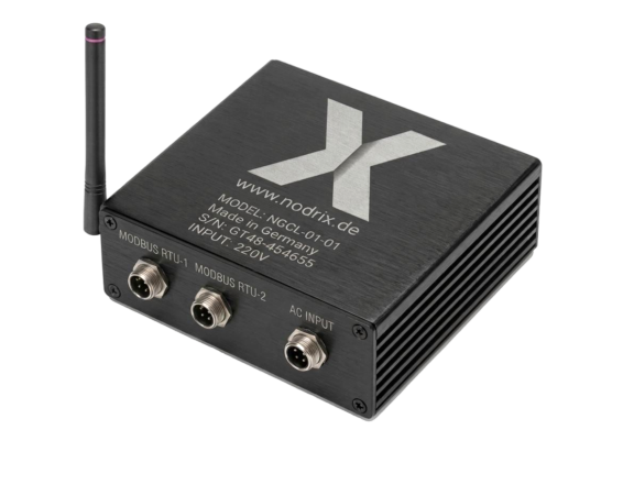
Exploded View

Every Layer. Every Component.

Scroll — the gateway builds up layer by layer.

NGC1-01-01 — Aufbau
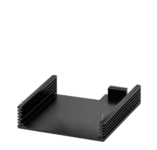
Housing Platine Deckel Cable Entry NGC1-01-01 komplett
Schicht 01
Aluminium Housing
DIN Rail housing · IP20 · 35 mm quick-mount · −20 to +60 °C
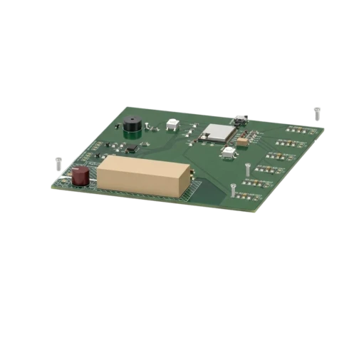
Schicht 02
Circuit Board (PCB)
Dual-Core 240 MHz · 16 MB Flash · 8 MB RAM · Hardware-AES · RS-485 Overvoltage Protection · High-Efficiency Regulator
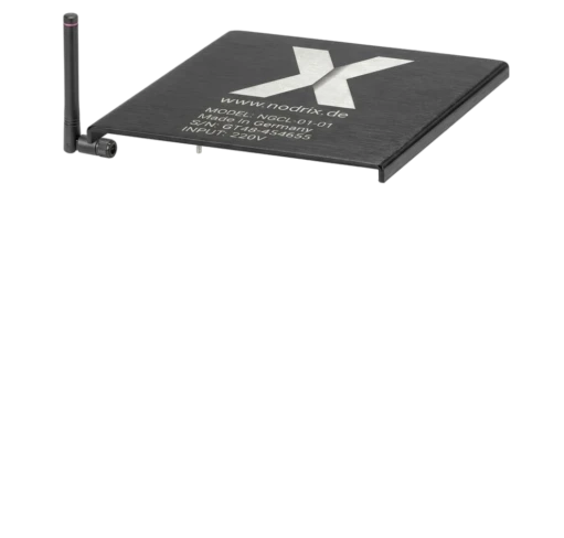
Schicht 03
Deckel & Befestigung
Aluminium-Deckel · Lasergravur · 4× M3 Schrauben
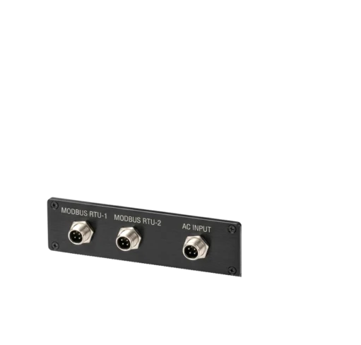
Schicht 04
Connections
M12-Steckverbinder · Modbus RTU-1/2 · AC Input 100–240 V
Edge Inference
FFT & MCSA directly at the gateway — no cloud round-trip needed.
🔒
Secure Cloud
MQTT v3.1.1/5.0 over TLS 1.2/1.3 with client certificate.
🛠
Embedded Web-UI
Browser-based configuration — no software installation.
⚙️
DIN-Rail
35 mm quick-mount in standard control cabinet.
Applications

In which solutions is the gateway used?

NGC is the heart of every Nodrix installation — wherever machine data is collected, pre-processed and streamed to the cloud.

System Architecture

From Sensor to Cloud

The NGC gateway forms the intelligent hub between the sensor nodes (NSTV), the current transformer inputs and the Nodrix Cloud Platform.

📳
NSTV-01-01
3-Axis Vibration
Pt100 Temperature
📳
NSTV-01-01 #2
Modbus RTU Slave
up to 300 m cable
📳
NSTV ×30 weitere
bis 32 Nodes pro Bus
RS-485
Modbus RTU
🖥
NGC Gateway
240 MHz · 8 MB RAM
Edge FFT & MCSA
Embedded Web-UI
Edge Inference Engine
6× CT Inputs
SCT-013 · 0–1 VAC / 0–50 mA
🔔
Piezo Alarm
Lokale Schwellwert-Alerts
Wi-Fi
MQTT/TLS
☁️
Nodrix Cloud
MQTT v3.1.1/5.0
TLS 1.2/1.3 · WSS
📱
Web-Dashboard
Live-Streaming
Alarm-Management
🔧
Embedded Web-UI
Browser-based
Configuration · no setup
Why NGC?

Edge Intelligence Outperforms Classical Solutions

Comparison with traditional PLC/SCADA-based condition monitoring approaches.

Feature NGC-Gateway Classical PLC Cloud-only IoT
Local Edge Analysis (FFT/MCSA)
No Cloud Round-Trip for Alerts
Commissioning without Software Partial
DIN Rail Direct Mount
Up to 32 Sensor Nodes per Bus Complex Gateway required
MQTT/TLS Cloud Connectivity
Power Supply 9–36 VDC 24 VDC fixed Variable
−40 °C to +85 °C operational Partial
Typical Installation Time ~15 minutes 4–8 hours 2–4 hours
Commissioning

Operational in 3 Steps

No laptop. No software. No network configuration expertise required.

1
🔩
Mount the Gateway
Snap the NGC onto the 35 mm DIN rail. Connect 24 VDC power supply via the screw terminals.
35 mm DIN Rail · Snap-On 24 VDC · Screw Terminals DIN Rail · IP40
2
🔌
Connect Sensors & CTs
Wire NSTV sensor nodes in series via RS-485. Plug current transformers (SCT-013) into the CT inputs.
RS-485 · bis 300 m GX12-4 Stecker 6× CT input · SCT-013
3
🌐
Browser Configuration
Connect to the NGC Wi-Fi access point, open a browser and enter slave IDs, baud rate, Wi-Fi credentials and cloud access data.
Wi-Fi AP · no cable Browser-only · no download MQTT-Credentials · ready
Specifications

All Details at a Glance

Choose between full technical data or direct access to documentation.

Edge-Processing & Speicher
CPU Architecture32-Bit Dual-Core RISC
Clock Frequency240 MHz
AcceleratorVector / DSP (FFT & MCSA)
Volatile Memory (RAM)8 MB Octal PSRAM
Non-Volatile Memory16 MB Quad SPI Flash
Local Alarm EngineOn-Board Piezo Buzzer
📊
Analog Inputs & MCSA
Analog Channels6× Single-Ended (CT-capable)
Application Capacity2× 3-phase or 6× 1-phase
ADC-Resolution12-Bit High-Speed
Sampling ModeSynchronous / Sequential
Input Level0–1 VAC / 0–50 mA
Signal ConditioningOn-Board Anti-Aliasing
🔋
Power Supply & Protection
Rated Input Voltage24 VDC
Operating Input Range9–36 VDC
Regulator TopologyHigh-Efficiency Switching
Internal Rails3,3 VDC & 5,0 VDC
Current Consumption< 80 mA @ 24 VDC
Reverse Polarity ProtectionIntegrated Hardware
Overcurrent ProtectionResettable PTC Fuse
Surge / Spike ProtectionTVS Array · IEC 61000-4-5
🔗
Kommunikation & Cloud
Downstream-Interface NGC11× RS-485 (Modbus RTU Master)
Downstream-Interface NGC22× RS-485 independent (Modbus RTU Master)
Modbus Framing8E1 (Standard), 8N1, 8O1, 8N2
WirelessWi-Fi 802.11 b/g/n (2,4 GHz)
Cloud-ProtocolMQTT v3.1.1 / 5.0 (TLS 1.2/1.3)
Live-StreamingSecure WebSocket (WSS)
Service PortUSB 2.0 Micro-B (with ESD protection)
USB Line ProtectionTVS-Array (5,25 V WM / 17 V Clamp)
Data Line ESD±15 kV (Air) · ±8 kV (Contact)
🖥
Embedded Web-Konfigurator
Hosting ArchitectureOn-Chip Embedded Web-Server
AccessBrowser-based · no software required
User InterfaceResponsive Web-Dashboard
Configuration OptionsSlave ID · Baud · CT Calibration · Wi-Fi · Thresholds
Security LayerPassword-protected admin login
📐
Mechanik & Einbau
Housing MaterialAluminium Extrusion
Dimensions154 × 145 × 55 mm
Mounting35 mm DIN Rail
Connection TerminalsPluggable screw terminals
USB MechanicsRight-Angle Through-Hole Tabs
RF AntenneU.FL → RP-SMA Panel-Mount
Protection ClassIP40
Operating Temperature−40 °C to +85 °C
Pricing & Request

Choose Configuration & Request Quote

Submit your request — you will receive a non-binding pro-forma offer by e-mail. All prices net plus VAT, exclusively for business customers.